
Passive Power-over-Ethernet
main characteristics:
• uses 'spare' wires 4,5,7 & 8 to transmit power over an Ethernet cable
• typically supports up to 100Mbit/s ('Fast Ethernet')
• requires an injector to turn separate data & power inputs into single Ethernet signal
• requires a splitter to get back the separate data & power from the merged Ethernet signal
• at 5V limited to approx. 20 meters due to passive components (no power/voltage regulation)
Passive PoE
Passive Power-over-Ethernet uses 'spare' wires 4, 5, 7 and 8 to transmit power. These wires are 'spare' because they are not used in 10/100M operation. A so called injector takes Ethernet and DC power as inputs and merges these onto a single Ethernet cable: data is kept on wires 1, 2, 3 & 6; power is put on wires 4, 5, 7 & 8. Typically DC- is on wires 4 & 5 and DC+ is on wires 7 & 8, however, as long as the injector and splitter conform to the same mapping it doesn't really matter how exactly the 4 spare wires are used (for this reason always use an injector and splitter that are sold together).On the other end a splitter takes the 'merged' data+power signal as input and splits this back into separate Ethernet and DC power outputs. Note that there is thus only actual power on the Ethernet cable in between the injector and the splitter. There is never power on the Ethernet input plug of the injector or the Ethernet output plug of the splitter, as only wires 1, 2, 3 and 6 are connected all the way through. This is also why passive PoE is limited to 10/100M operation (for 1000M operation additional wires 4, 5, 7 and 8 are required for data transmission itself) and also why passive PoE injectors/splitters can safely be used with gigabit Ethernet equipment (they simply behave like an Ethernet cable with only 4 wires connected).
Voltage drop and maximum length
Because with passive Power-over-Ethernet the power is put directly on the 4 wires of the Ethernet cable what comes out at the splitter end is what goes in at the injector minus the loss incurred from cable resistance. This voltage loss, also known as voltage drop, is directly dependant on the current:Vdrop = I·R where I is the current in amperes and R is the wire resistance in ohms. This is especially important for Raspberry Pi applications drawing substantial current - e.g. having several USB peripherals connected - as the more current you draw the less distance you can cover with passive PoE, as is depicted in the following table:| current1 | cable length | resistance2 | voltage drop | output voltage at splitter3 |
| 0.4A | 5M | 0.43Ω | 0.17V | 5.03V |
| 0.4A | 10M | 0.85Ω | 0.34V | 4.86V |
| 0.4A | 15M | 1.28Ω | 0.51V | 4.69V |
| 0.4A | 20M | 1.71Ω | 0.68V | 4.52V |
| 0.4A | 25M | 2.14Ω | 0.85V | 4.35V4 |
| 0.4A | 30M | 2.56Ω | 1.03V | 4.17V4 |
| 0.6A | 5M | 0.43Ω | 0.26V | 4.94V |
| 0.6A | 10M | 0.85Ω | 0.51V | 4.69V |
| 0.6A | 15M | 1.28Ω | 0.77V | 4.43V4 |
| 0.6A | 20M | 1.71Ω | 1.03V | 4.17V4 |
| 0.6A | 25M | 2.14Ω | 1.28V | 3.92V4 |
| 0.8A | 5M | 0.43Ω | 0.34V | 4.86V |
| 0.8A | 10M | 0.85Ω | 0.68V | 4.52V |
| 0.8A | 15M | 1.28Ω | 1.03V | 4.17V4 |
| 0.8A | 20M | 1.71Ω | 1.37V | 3.83V4 |
| 1A | 5M | 0.43Ω | 0.43V | 4.77V |
| 1A | 10M | 0.85Ω | 0.85V | 4.35V4 |
| 1A | 15M | 1.28Ω | 1.28V | 3.92V4 |
| 1.2A | 5M | 0.43Ω | 0.51V | 4.69V |
| 1.2A | 10M | 0.85Ω | 1.03V | 4.17V4 |
| 1.2A | 15M | 1.28Ω | 1.54V | 3.66V4 |
1note that a Raspberry Pi by itself typically draws about 0.4A, see raspberrypi.stackexchange.com/questions/341/whats-the-current-draw-and-supply-voltage-tolerance
2combined resistance of 2 copper wires of 24AWG over 2 x cable length (round trip), see also calculating combined wire resistance
3assuming input voltage at injector of 5.2V, which is ~ what a typical 5V adapter will supply
4the Raspberry Pi itself will work with as little as 4V, however most USB peripherals need more
You can use a voltage drop calculator to calculate the voltage drop for custom cable types and lengths. Above table assumes using proper CAT5e cable, that is with pure copper conductors and a wire diameter of 24AWG (0.2"/0.5mm single wire). Note that some cables sold as CAT5e do NOT meet these specifications (they have alluminium wires and/or single wire diameters of less than 0.2"/0.5mm). While IEEE 802.3af Power-over-Ethernet can cope well with most of such cables, passive PoE performance is negatively impacted by them.
related products
€12,50
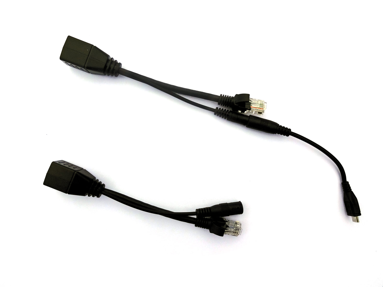
Raspberry Pi/micro-USB PoE cable set